BLUETTI Charger 2: Solar and Alternator Charging Limits
Check the BLUETTI Charger 2's documented DC-DC output, PV voltage boundary, and receiving-station path without assuming universal vehicle or panel compatibility.
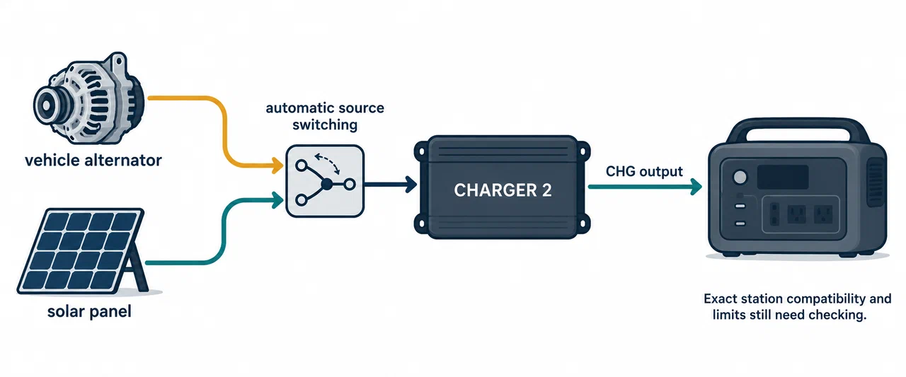
The BLUETTI Charger 2 is a DC-DC charger that connects a vehicle charging path and a solar path to a compatible portable power station. The manual describes up to 1,200 W charging output, automatic switching between alternator and solar charging, and reverse charging through the BLUETTI app. Those features belong to this charger and its documented connections; they do not establish a universal station, vehicle, or panel compatibility list.
Read the solar and receiving-station limits separately
For the solar connection, the Charger 2 manual specifies a PV open-circuit voltage range of 13–50 V. Its connection diagram illustrates a 600 W panel profile at 50 V and 20 A. That diagram is an example, not approval for every panel with the same wattage or for an array whose open-circuit voltage exceeds the stated PV boundary. Check the panel’s full electrical data and the exact charger instructions.
The diagram also shows a receiving portable-station path rated up to 1,200 W, 12–56 V, and 24 A. That path describes the charger-to-station connection in the diagram. It does not name a complete set of supported station models or mean that any unit with a similar voltage range can accept the charger. The station’s input limit, connector, polarity, cable, and model-specific charging modes remain part of the check.
| Part of the system | Manual detail | Interpretation |
|---|---|---|
| Charger output | Up to 1,200 W | Manufacturer maximum; actual operation depends on the compatible system |
| PV input | 13–50 V open-circuit voltage | Keep the proposed panel arrangement within the charger’s stated PV boundary |
| Illustrated panel | 600 W, 50 V/20 A | One connection-diagram example, not a generic panel approval |
| Receiving station path | Up to 1,200 W, 12–56 V/24 A | Diagram values for the charger-to-station path; verify exact station support |
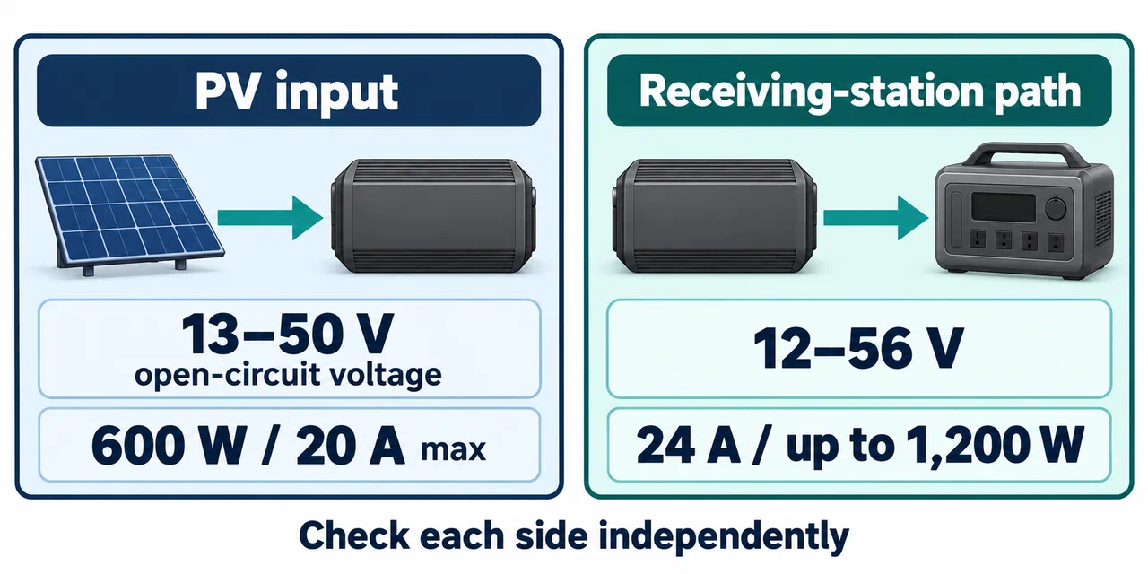
Do not substitute the station’s input window for the charger’s PV limit or the other way around. Both sides must match the actual cable and connection path. A total watt figure cannot replace voltage, current, connector, and polarity checks.
Understand the vehicle and mode boundaries
The manual describes alternator and solar input paths with automatic switching between sources. It also describes a reverse-charge mode controlled through the BLUETTI app. Automatic switching does not mean the two sources are always combined at full output, and an app mode does not confirm that an unspecified battery or vehicle is compatible.
Charger 2 uses different connections and cables for car-battery, PV, BLUETTI-product, DC-hub, and smart-alternator configurations. The selected diagram must match the equipment and system in front of you. The manual’s maximum output is not a vehicle alternator rating, a universal charging rate, or proof that a portable station can receive that power.
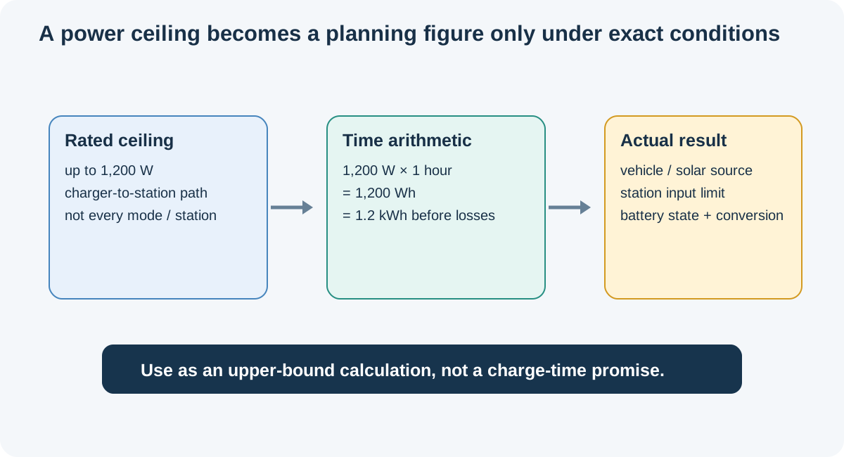
For planning, treat 1,200 W as a ceiling only when the exact charger mode and receiving station path both permit it. At that ceiling, one hour corresponds to 1.2 kWh before conversion losses; this is arithmetic, not a promise of delivered energy. Actual time and energy depend on the connected system, source conditions, battery state, and charging behavior. Keep enough reserve for the trip or use case if output varies.
Make a compatibility check before relying on it
Identify the Charger 2 model and manual revision, vehicle and charging source, selected solar panels, receiving station, each cable and connector, and the intended app or operating mode. Confirm PV open-circuit voltage, station input voltage/current/power, connector polarity, and the connection diagram for the exact arrangement. When a product or limit is not identified in the documentation, ask BLUETTI with the model labels rather than transferring a diagram from another station.
The manual gives selected connection examples, not a complete vehicle alternator-capacity table, cable and fuse matrix, or supported-station list. It does not supply a universal DIY installation procedure. Follow the current manufacturer instructions for the exact installation and use qualified vehicle support when required. This article does not provide vehicle wiring or installation steps.
If the system combines solar and driving, plan from the charging windows and expected loads rather than adding advertised maximums. A solar panel can be shaded, angled, or limited by weather; a drive can be shorter or slower than planned. The charging-source comparison and multi-day solar plan provide a reserve-first planning method.
Key Points
- The manual describes up to 1,200 W Charger 2 output, but that value is not a universal rate for every vehicle and station.
- Keep the PV open-circuit voltage within 13–50 V and verify the full panel data.
- The 600 W, 50 V/20 A PV profile and 12–56 V/24 A receiving path are diagram examples, not a complete compatibility matrix.
- Automatic source switching and app-controlled reverse charging are charger features, not universal connection approvals.
- Confirm exact vehicle, panel, station, mode, cable, connector, and polarity in current manufacturer instructions.