Sump Pump Startup, Cycling, and Power Station Runtime
Assess sump-pump runtime by identifying the exact pump, measuring startup and cycle energy, and keeping flood protection separate from a battery estimate.
A sump pump is a motor load whose runtime depends on more than the pump’s running watts. It must start, move water against the actual head and discharge conditions, and repeat those cycles as water enters the basin. A battery calculation cannot guarantee flood protection if the pump cannot start, the station trips, inflow rises, or the backup arrangement fails.
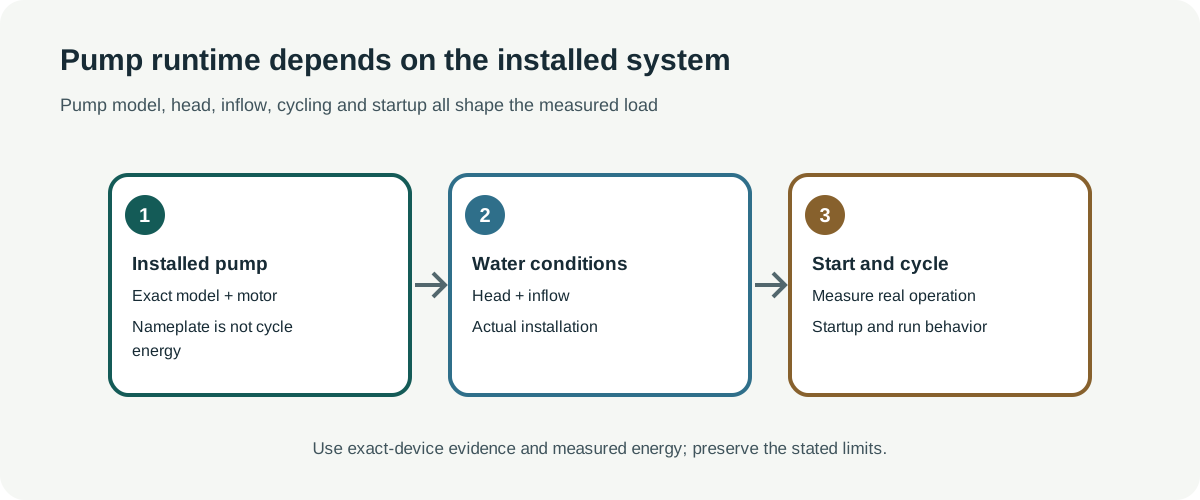
Identify the installed pump
Read the complete pump and controller labels. Record voltage, frequency, horsepower, full-load current, automatic or manual switching, cord, controller, and any dedicated backup battery system. Maximum flow and maximum head are separate points on a manufacturer performance curve; neither tells you the flow at your property’s total head.
Named Zoeller models show why the exact row matters. The Model 49 sheet lists 4.0 A at 115 V and 60 Hz, while the Model 98 sheet lists 9.4 A for 115 V versions and 4.7 A for 230 V versions. The Model 53 family lists 4.8–9.7 A across its 115/230 V variants, up to 19.25 ft head and 43 GPM; those maxima do not establish a particular installation’s duty. Those current values are not measured running watts or startup current. Liberty’s HT40 engineering sheet makes the distinction explicit for its named 115 V variants: 12 A full-load current and 23 A locked-rotor current. Do not generalize those figures to another pump or turn current directly into battery runtime.
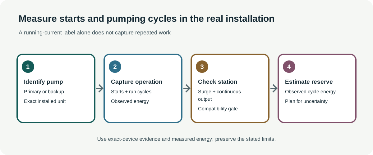
Measure starts and real pumping cycles safely
A meter reading from a pump that is already running does not show whether an inverter can handle startup. Check the pump and station manuals for continuous output, surge capacity, waveform, grounding, and any permitted power path. Where a measurement is needed, have a qualified person use suitable equipment in a safe setup; sump installations combine water and mains electricity.
A useful energy record includes several automatic pump cycles under representative water level and discharge conditions. Note how often the pump starts, how long it runs, the observed energy per cycle, and whether the station reports overloads or shuts down. Do not deliberately create a flood condition to collect data. A test in a low-water basin cannot establish behavior during heavy inflow.
If you have measured energy per cycle, estimate demand from the expected number of cycles and add a reserve. If you only know running watts, average watt-hours from an unrelated pump, or a battery’s advertised capacity, the key inputs are still missing. A pump’s motor start and the station’s usable energy are separate checks.
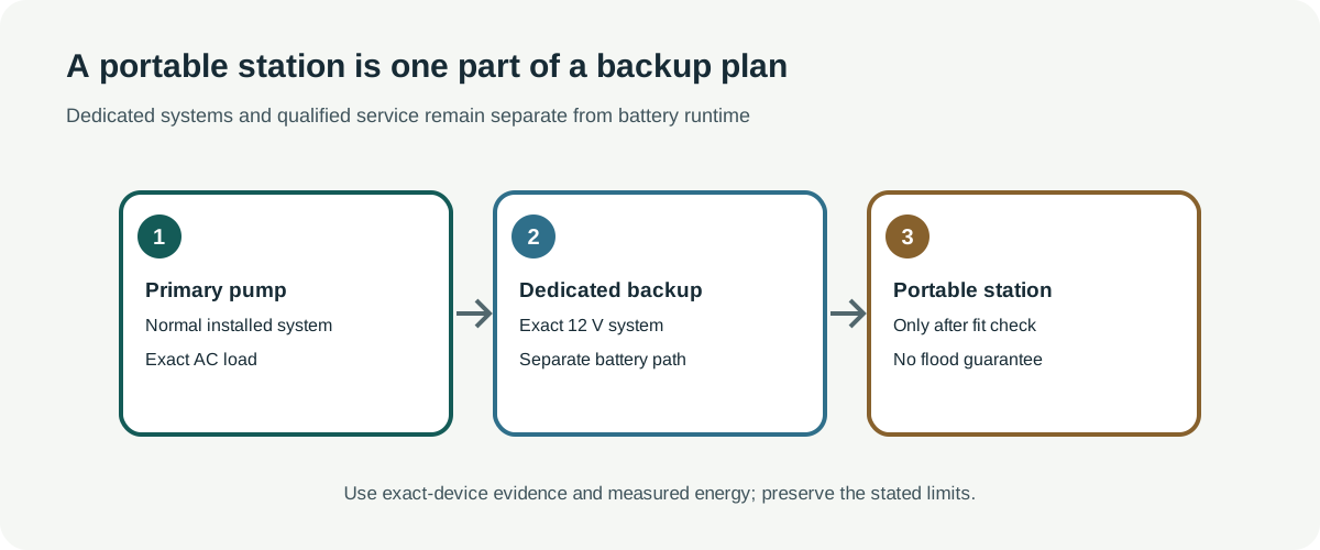
Keep dedicated backup systems distinct
Some sump installations use a dedicated 12 V backup pump and controller. Zoeller’s Aquanot Key 507/73 manual reports 6.5 hours of continuous running with its recommended battery and a separate 10% duty-cycle example over two days. The newer Aquanot Spin 508 sheet gives approximately 5.5 hours continuous running with a specified 175-minute-reserve battery and warns that some marine-standard DC test values can exceed actual battery performance. These are manufacturer system-specific examples, not portable-station tests or promises for another basin, and they do not permit bypassing the installed controller. Follow the exact system manual for grounding, circuit protection, water type, testing, and qualified service.
Named pump and backup profiles illustrate why an installed system must be identified precisely. Zoeller’s M73 sheet lists an automatic 1/3 HP, 115 V, 60 Hz submersible pump with a 5.5 A specification; that is not its locked-rotor or station-start demand. Zoeller Models 81, 82, and 84 are pedestal pumps with above-pit motors, and their sheet does not provide a directly comparable startup current. Do not transfer one design’s figures to the other.
Pentair’s Simer A5300 is a separate installed 12 V DC backup system supplied by a 115 V AC charger. Its manual pump curve lists 45, 34, and 21 GPM at 0, 5, and 10 ft of head, with zero flow at 15 ft; Pentair also lists up to 2,700 GPH and 1,260 GPH at 10 ft. These are system performance points under the stated conditions, not battery duration. The A5300 is not a portable-station interface or a substitute for a primary pump. Follow the exact system manual and keep the controller, battery, alarm, and installation protections intact.
Do not replace a primary pump, wired backup, alarm, or transfer arrangement with a portable station unless the pump manufacturer and a qualified electrical professional confirm the complete setup. Keep an alternate plan for rising water, station failure, a stuck float, loss of recharge, or a pump that cannot keep up.
Before relying on an estimate
Confirm the exact pump and regional voltage, check startup and continuous-output requirements, measure representative cycle energy safely, and test the complete approved arrangement before an outage. Include the station’s reserve and any controller load. If the installation is critical, arrange a non-battery fallback and qualified service plan. A runtime estimate describes a test condition; it is not a guarantee against basement flooding.